


DC 9V SMT Soldering Test Kit Electronic Practice Set
96

 Direct purchase from the factory
Tuta Solutio

 Donum Gratis
 Politica Missilis
 Politica Reditus
Donum Gratis
Salve ad Roymall, tuum destinatum ad dona premium. Gratias agimus pro tuo auxilio, et offerimus donum gratis cum omni emptione. Paratus ad explorandum nostram collectionem? Perlege nostra selectio, fac ordinationem tuam, et expecta donum tuum gratis cum emptione.Politica Missilis
Processamus ordinationes intra 2 dies.Norma missilis tempus est 5-7 dies laboris.Tempus missilis potest variari secundum destinationem.1. Politica Reditus
Accipimus solum res emptas ex roymall.com. Donum gratis non potest reddi. Res debet esse non usata et in originali packaging.Processamus reditus intra 3-5 dies laboris post receptionem.Res personalisatae non possunt reddi.Contacta nos: service@roymall.com vel Whatsapp: +86193598494712.Politica Pecuniae Redditae
Accipies plenam pecuniam redditam post receptionem et inspectionem. Sumptus missilis non redditur.Contacta nos: service@roymall.com vel Whatsapp: +8619359849471
{"code":"00","result":"


Description:
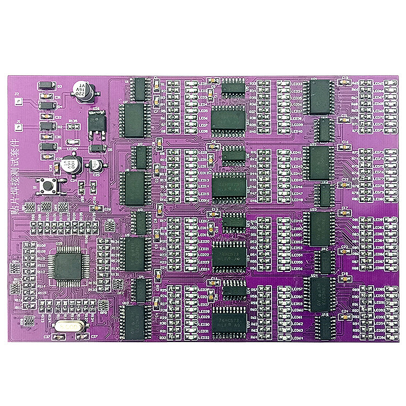
1. J1 and J2 are the power supply input terminals of the entire SMT board. It can work normally when connected to AC6V or DC9V. When working normally, all LED lights in this kit can work normally. At first, each group of LEDs flashes with water, and then flashes at intervals, and finally all Light up all the LEDs, then flash again, and cycle like this to check whether the LEDs are working and whether they are soldered well. If it is found that the corresponding LED does not flicker, it means that there is a welding error or a false welding.
2. The AC6V power supply is rectified by D1-D4 diodes, and then through each filter capacitor to pin 1 of the voltage regulator chip 78M05 (LED97 is always on, the rectifier circuit is working normally), and the output of DC5V is supplied to the whole test circuit through pin 3.
3. This test circuit is controlled by a single-chip microcomputer to work with 12 groups of 8-bit LED lights. Each group is composed of 1 74HC573 and 74HC164. One group can control 8 LEDs, 12 groups in total. Figure 1 is the control schematic diagram of one group. When working normally, all LED lights are on and can flash.
Specifications:
Product Name: SMD Soldering Test Kit
PCB material: FR-4PCB board
PCB size: 145*100MM
patch tape connection test
Power supply mode: DC DC9V
Applicable objects: junior welding patch personnel
Component Description: Common patch components are used
Products related to this item
Loading related products...
❮
❯
Videos for similar product
Loading product videos...
❮
❯
Electronics Ranking


Description:
1. J1 and J2 are the power supply input terminals of the entire SMT board. It can work normally when connected to AC6V or DC9V. When working normally, all LED lights in this kit can work normally. At first, each group of LEDs flashes with water, and then flashes at intervals, and finally all Light up all the LEDs, then flash again, and cycle like this to check whether the LEDs are working and whether they are soldered well. If it is found that the corresponding LED does not flicker, it means that there is a welding error or a false welding.n
2. The AC6V power supply is rectified by D1-D4 diodes, and then through each filter capacitor to pin 1 of the voltage regulator chip 78M05 (LED97 is always on, the rectifier circuit is working normally), and the output of DC5V is supplied to the whole test circuit through pin 3.n
3. This test circuit is controlled by a single-chip microcomputer to work with 12 groups of 8-bit LED lights. Each group is composed of 1 74HC573 and 74HC164. One group can control 8 LEDs, 12 groups in total. Figure 1 is the control schematic diagram of one group. When working normally, all LED lights are on and can flash.
Specifications:
Product Name: SMD Soldering Test Kit
PCB material: FR-4PCB board
PCB size: 145*100MM
patch tape connection test
Power supply mode: DC DC9V
Applicable objects: junior welding patch personnel
Component Description: Common patch components are used
- Introductio
- De Nobis
- Pactum Usoris
- Ius Auctoris
- Cooperatio
- Promotio Negotii
- Nexus Amici
- Recruitatio Part Time
- Auxilium
- Quomodo Emere
- Opinio
- Munus Consultor
Accipe nuntios et 15% discount in prima emptione.
Elige Monetam

Elige Linguam
Nexus: